Hi Everyone!
It's been a while since I've posted any "How To's" here in the forums, so I decided to do a write-up on how to build a base station antenna. . . that you can stick in your ruck sack. These are extremely good antennas for a number of reasons. If you read any of my other posts, you'll know that antenna length is extremely important when it comes to whichever frequencies you want to use. So. . . what better kind of antenna is there, than one made from measuring tape?! Just pull out the length you need, and you're ready to roll!
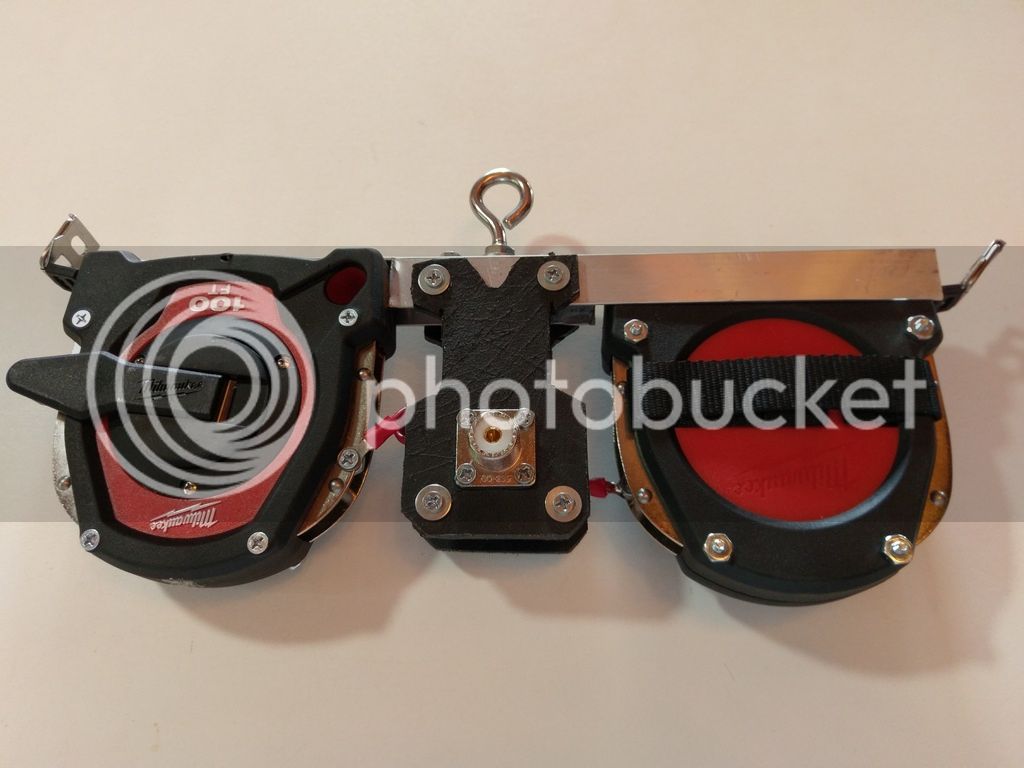
Figure 1. Here's what it looks like.
Yes, it's a dipole. A report from a similar design indicated being able to easily reach Europe from the east coast USA on just 5 watts!
Instead of writing up a boring list of the items you'll need, I'll just explain it along the way. The reason for this, is because no two antennas are the same, so your requirements might be different. (To be fair, people have been building antennas from tape measures for some time, but they all seem to fall short somehow. This time, we're not cutting any corners.)
I'm using two Milwaukee brand 100ft. steel tape measures. You'll want metal tape measures, for obvious reasons. I chose these because I saw that they can be disassembled easily, and because they have two metal parts on the sides that hold the tape in place. You'll want to work with something similar - don't buy a tape measure that's glued together. . .
Step 1: Disassemble, and drill a couple of holes in the bottom for screws.
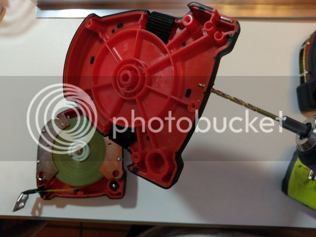
Figure 2: This is what it should look like.
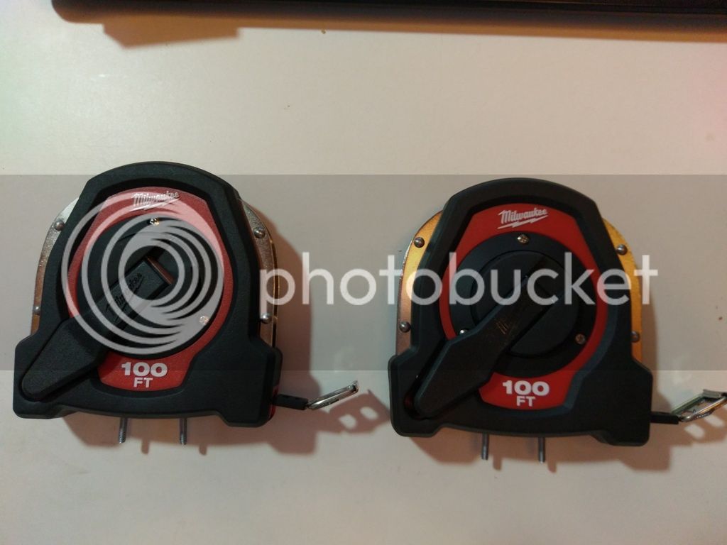
Figure 3: Do the same for the other tape measure as well.
Step 2: On an aluminum L-shaped bar, drill holes to match your screws.
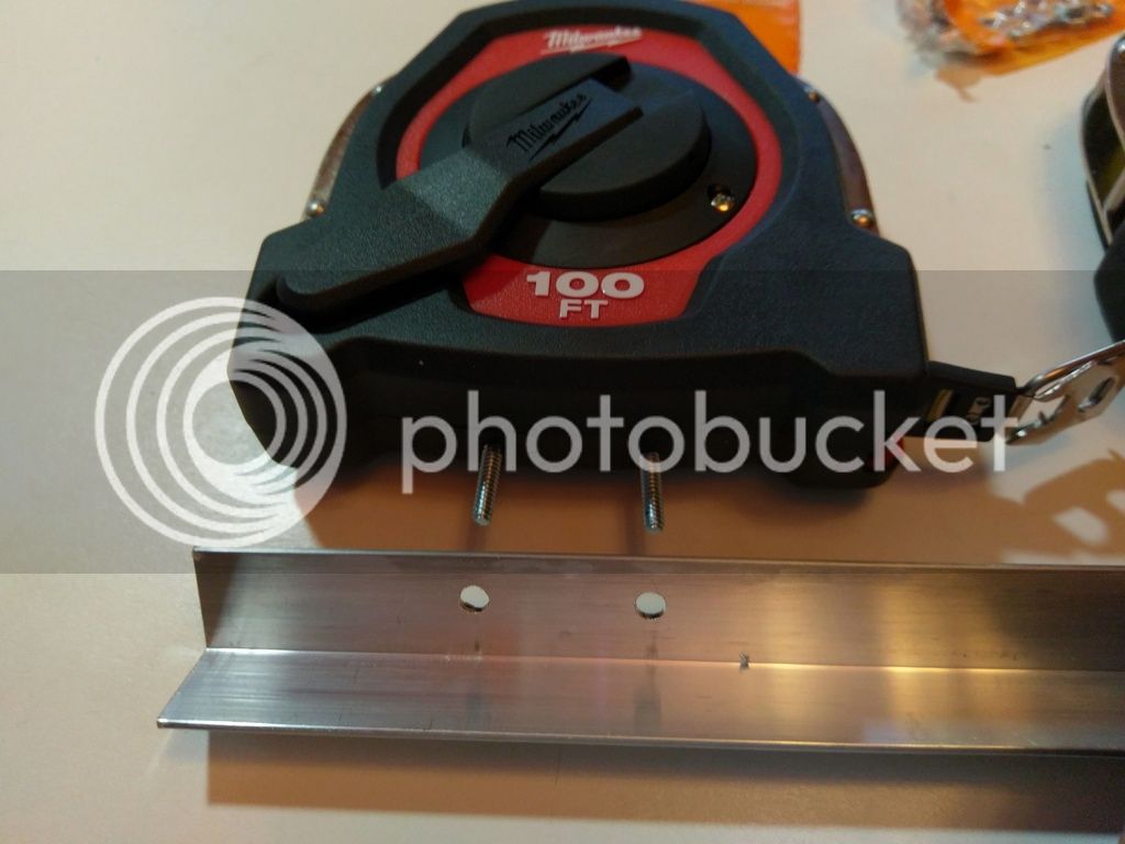
Figure 4: It's not rocket science.
This will need some explaining, though. You can get these in 1-yard segments down at the hardware store for cheap. As you can see in the picture, I started at the end of the segment, and left about 6 inches of it coming from the side, and then cut off the rest. If you stood it upright, it would resemble a lowercase "d", that is to say. Do the same for the other tape measure. You should have two separate and identical "d" shaped pieces. . .
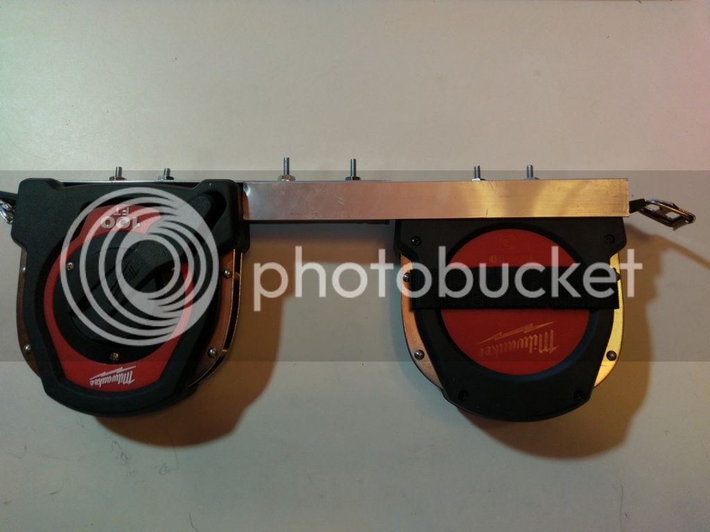
Figure 5: Put the two pieces together.
. . . so that you can attach the two together. Flip one over facing down, and slide the two railing parts together. You'll need to drill a couple of holes that line up through both pieces and attach with screws and nuts. So far, so good?
Not really. Everything up until this point was just for "fitment". We're going to have to take it all apart again.
Step 3: Electrical Work in the Innards
The thing is about tape measures, is that they're coated with a protective layer. Usually a good one too. If you were to use it as is, the radio signal wouldn't know which way to go. We've got to get it to travel across the coil of tape, not through it, going around in a coil. So. Let's do something conservative with that protective layer and get that radio signal traveling the way it's supposed to.
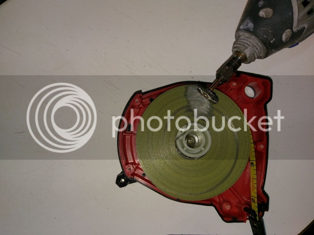
Figure 6: I used a Dremmel with a wire brush attachment to remove some coating.
Take apart your tape measures, and get to work! You can use sandpaper, brillo pads. . . whatever it takes to get that coil to shine!
Figure 7 (removed due to max photo limit): Here's the end-product. It's not perfect, but it works just fine.
As you probably noticed, my tape measure has two metal pieces on both sides which keep the coiled tape aligned properly. I've decided to use that to my advantage. The thing is, though, it's not a tight fit. I can't depend on the tape carrying a radio signal across the coil as it is. I need some kind of metal that will run across all of it, from one of those metal pieces to the other, and yet, still allow for the tape measure to function like a tape measure. So I came up with an idea. . .
Figure 8 (removed due to max photo limit): It just so happens that I had a cup that is precisely the same diameter as the coil. Note the two metal retaining parts.
And so, I went searching for the thinnest cardboard I could find. It turned out to be a shoebox lid. I traced the cup, and cut out a circle, trial and erroring my way cutting the inside circle, until I came up with this:
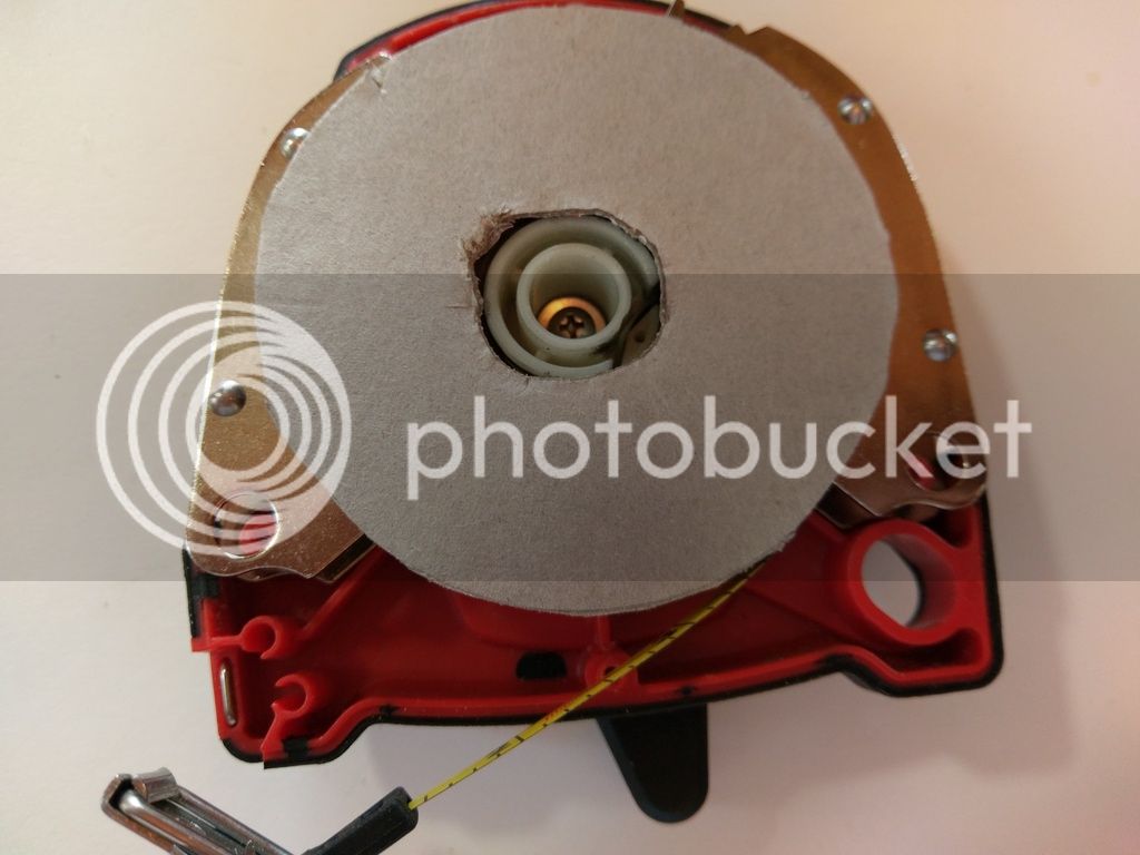
Figure 9: Just keep trimming with scissors until it's right.
Now is a great time to praise foil tape. I picked some up at the local auto parts store, but you can probably find it at the hardware store too. You'll never know when you need it, and this stuff has been sitting on the shelf for years.
Figure 10 (removed due to max photo limit): How I love this stuff!
The direction we're going here, should be apparent. Take the foil tape, and use it to cover your cardboard disk that you cut out.
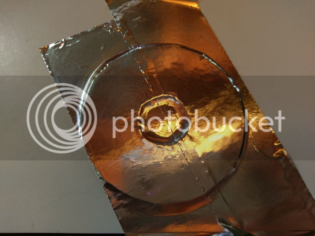
Figure 11: Like this.
Once you've done that, trim the edges and stick it back into the tape measure.

Figure 12: Now that you've inserted your "metal disk" into the tape measure, it's going to be tighter than it was - meaning, a bit difficult to reel the tape back in. So, some dielectric grease will provide some lubrication, without screwing with the conductivity of what you just created as normal grease will.
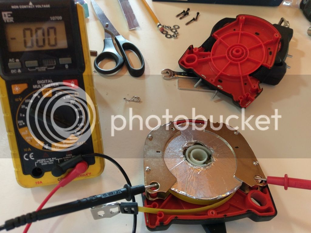
Figure 13: Test conductivity with a multi-meter to ensure that a radio signal is going to travel across the coil, and not around it.
Rinse, and repeat for the other tape measure.
Step 4: Exterior Electrical Work
I started by drilling a hole through one of those metal retainers, and attached a connector, to be sure that it would work.
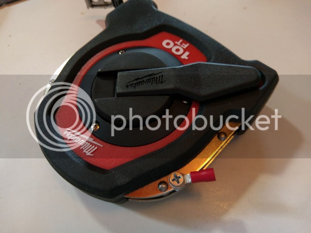
Figure 14: Like so.
Then, I tested for conductivity, this time, from the connector to the end of the tape. Just to be really, really sure.
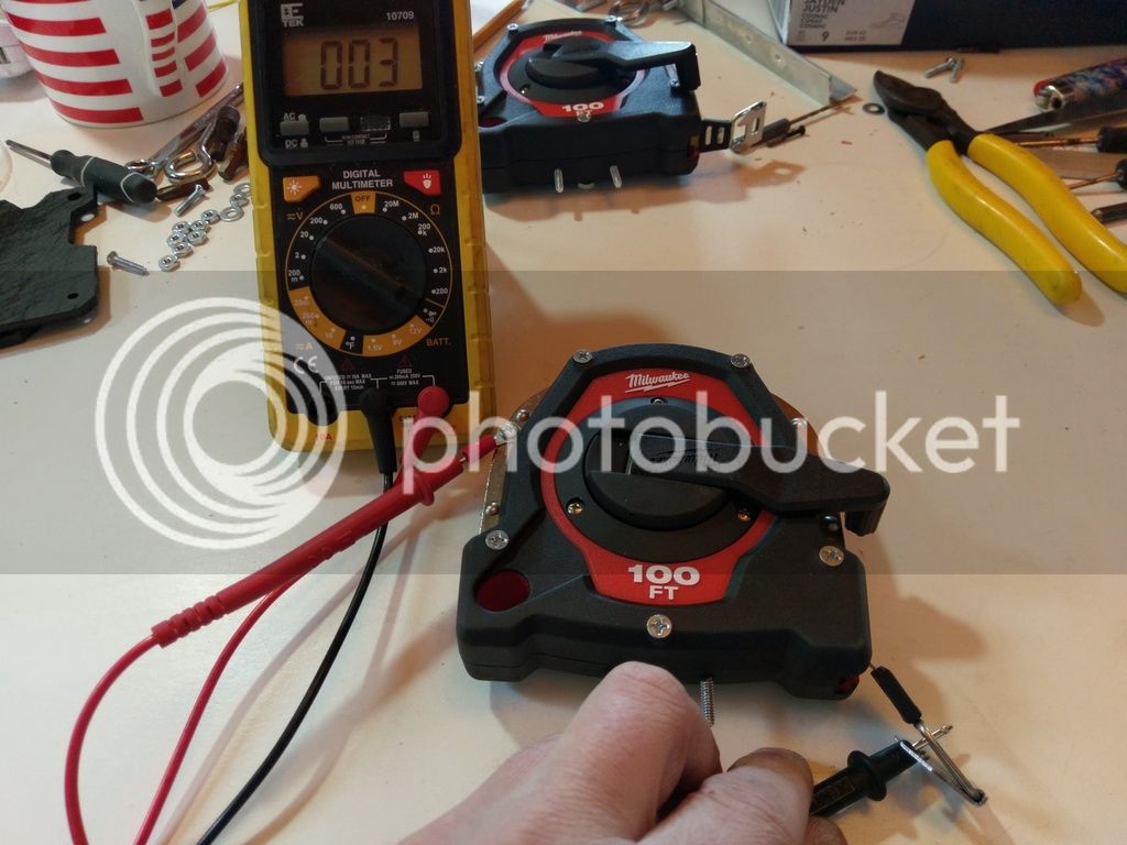
Figure 15: Conductivity test.
Step 5: Cutting Board Reigns!
It's the go-to insulator for all home-brew antennas. It's amazing stuff. You can cut it into any shape you want, it's strong, etc. I just love to destroy plastic cutting boards. So, I put the antenna back together, just to get an idea of how much room I left for myself between the two tape measures. While you're building yours, it might not be a bad idea to measure that out early. And how did I cut it? With the Dremmel, of course! But a small hacksaw will work too - whatever you can find.
Figure 16 (removed due to max photo limit): I started with two rectangles about this size. I clamped them together, drilled holes in the corners, and measured out where I want to put my SO-239 connector.
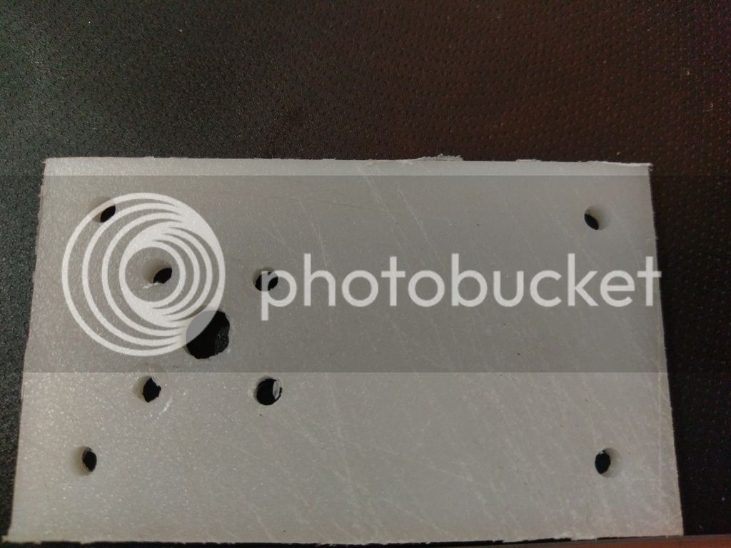
Figure 17: Then, I drilled holes for the connector. No measuring. I just eye-balled it.
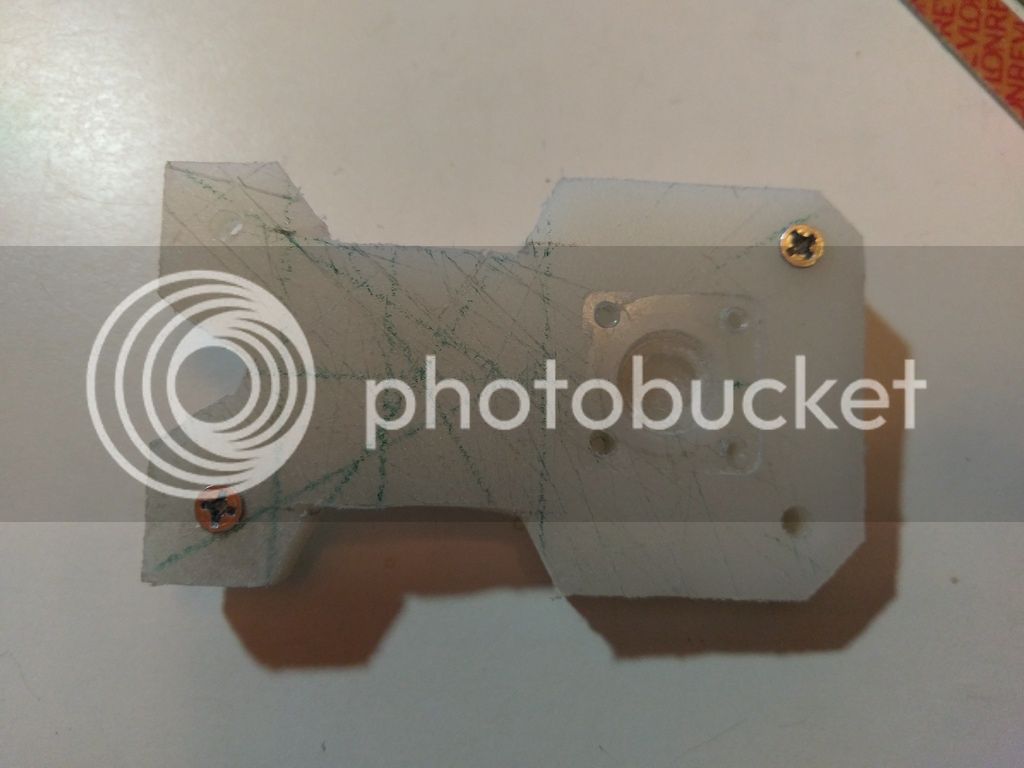
Figure 18: After some time, I did some geometry for looks. Rectangles are boring to look at. Note where I attached the connector, and used a torch to gently heat it so that it seats into the plastic perfectly. It never came out perfect, but then again, I'm not a CNC machine either.
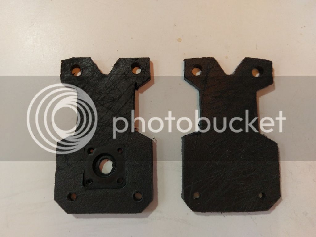
Figure 19: And some black engine paint that I had sitting around for the final touch.
Step 6: Connecting It All Together
Now we're going to take the cutting board assembly, and . . . assemble it. To start with, go ahead and install the SO-239 connector to the board. Then, we'll need two pieces of wire - I used about 12 inches of solid copper wire, but they can be shorter.
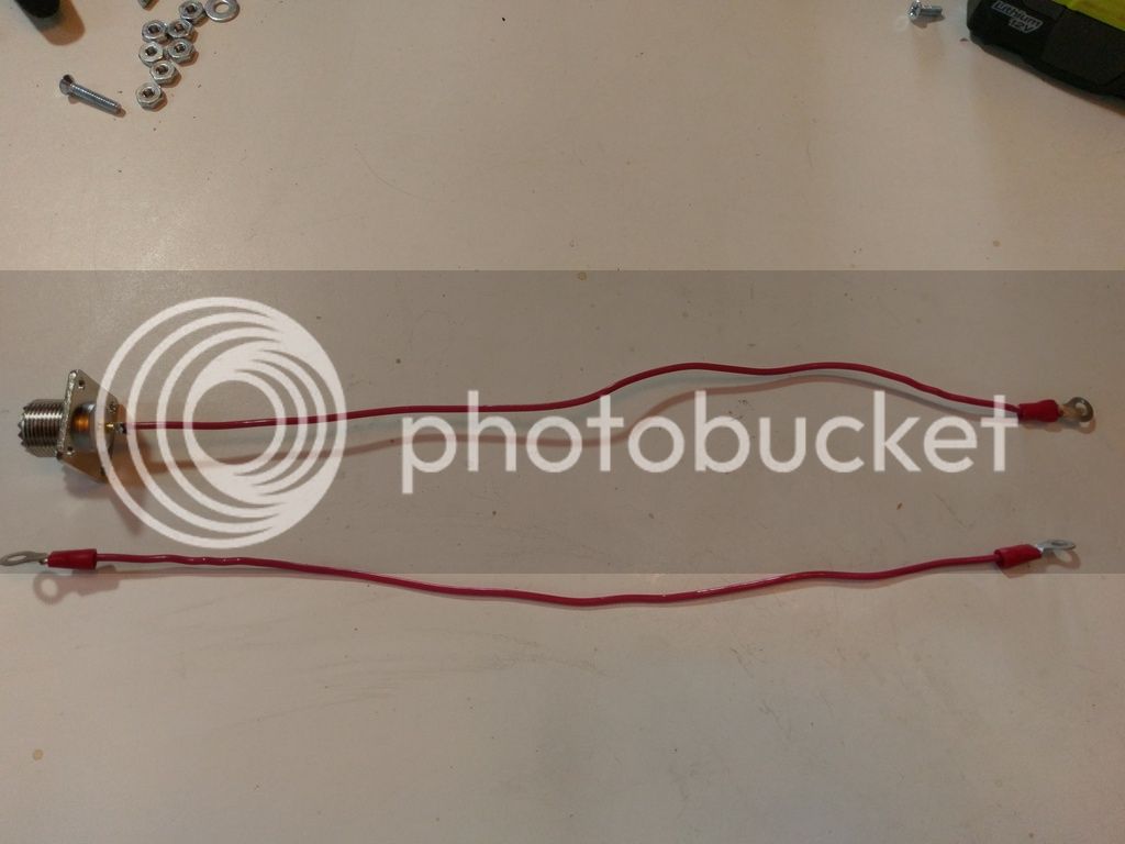
Figure 20: On one wire, solder two connectors, and on the other, just one connector with the lonely end soldered to the back (center) of an SO-239 connector. The other wire is connected to one of the screws.
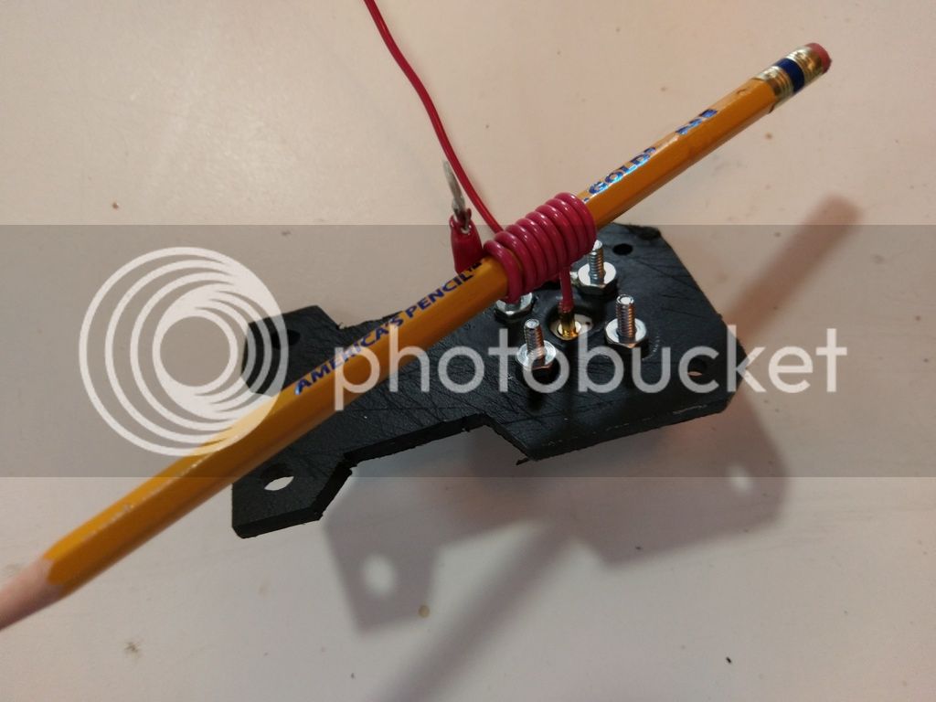
Figure 21: Once you installed the wires on the back of the connector, shorten them by coiling them around a pencil.
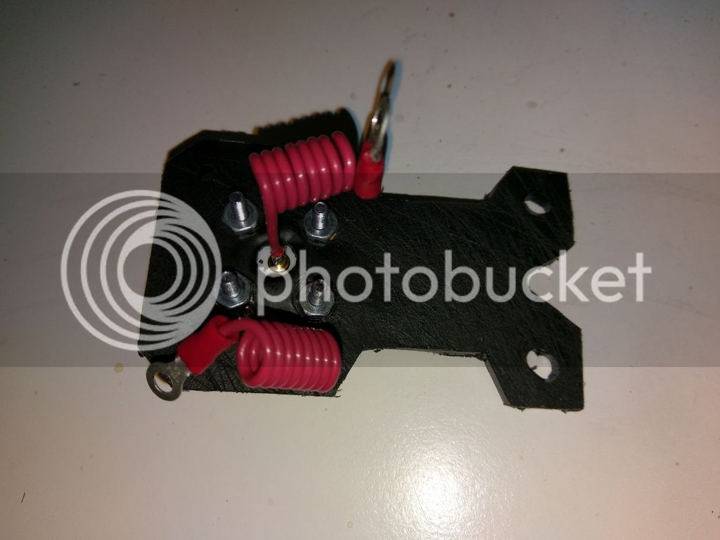
Figure 22: So that it comes out looking like this.
Now it's time to attach the cutting board assembly to the frame. This will require drilling some holes all the way through both pieces. I made sure to use larger holes than usual, in case it comes out crooked. That way, you can adjust it and tighten it down, and the washers conceal the irregularity in the holes.
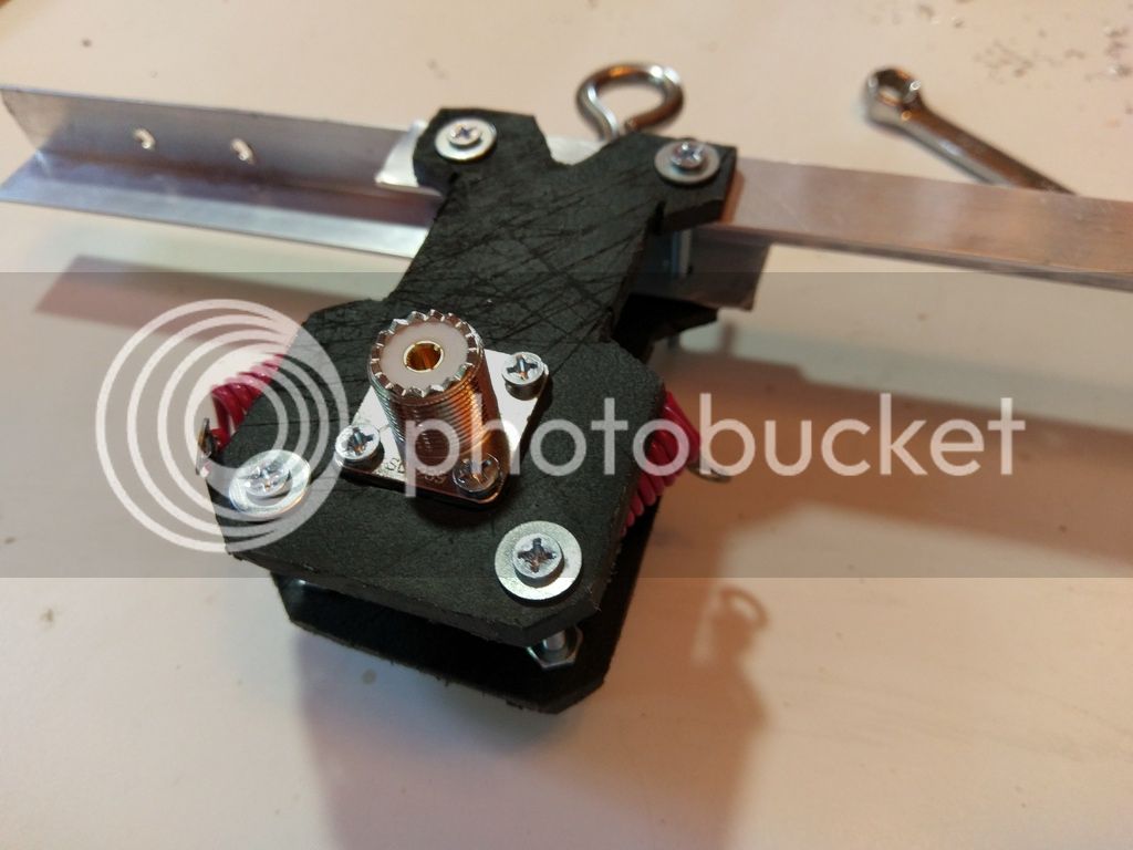
Figure 23: Note that the bottom screws have nuts on both sides of both boards. These can be adjusted to give you the perfect gap. Once you have the right gap, tighten it all up. Also note the loop thingy that I installed at some point to hang the antenna from.
Remember those holes you drilled in the sides of the tape measures? Go ahead and connect your wires. It doesn't matter which wire goes to which tape measure.
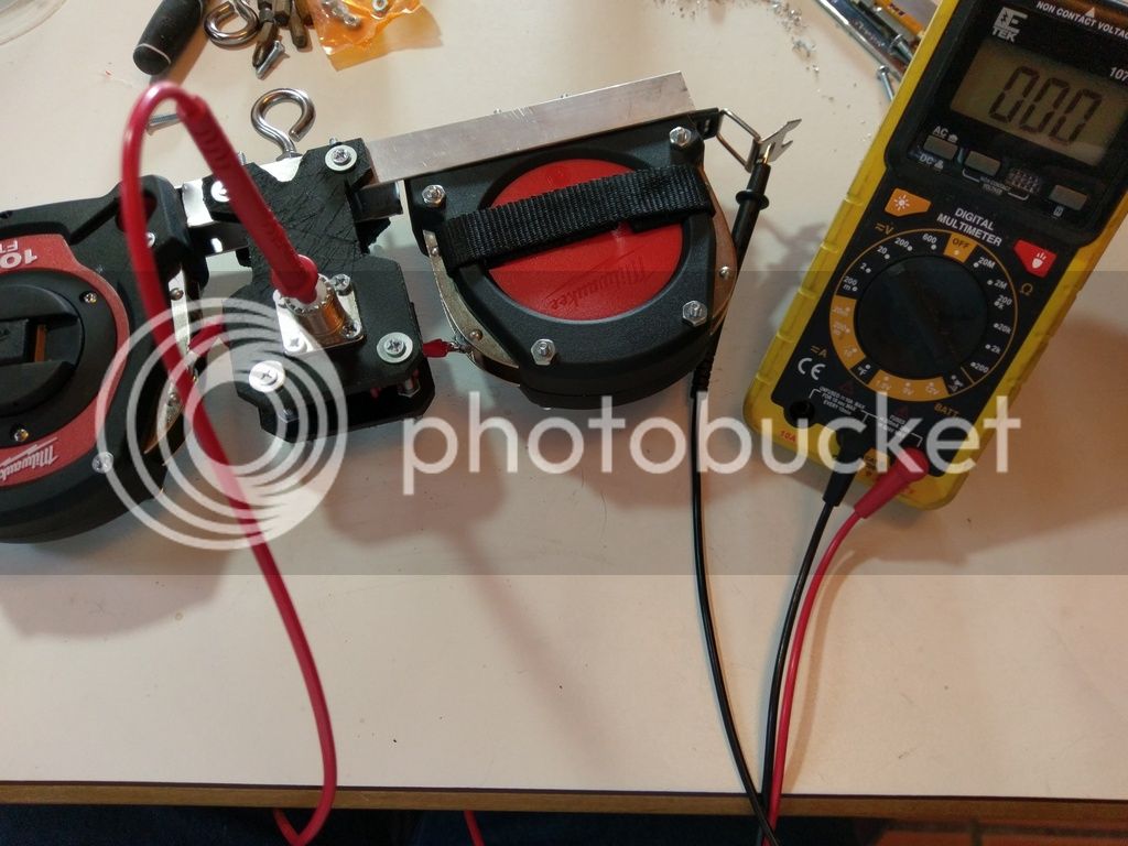
Figure 24: If you did this correctly, you should be able to get continuity from the center of the SO-239, to the end of one of the tape measures. The rest of the SO-239 should have continuity with the end of the other.
So, what length do you need to use? For that, just use a dipole calculator!
Like always, if you have any questions, please feel free to ask.
It's been a while since I've posted any "How To's" here in the forums, so I decided to do a write-up on how to build a base station antenna. . . that you can stick in your ruck sack. These are extremely good antennas for a number of reasons. If you read any of my other posts, you'll know that antenna length is extremely important when it comes to whichever frequencies you want to use. So. . . what better kind of antenna is there, than one made from measuring tape?! Just pull out the length you need, and you're ready to roll!

Figure 1. Here's what it looks like.
Yes, it's a dipole. A report from a similar design indicated being able to easily reach Europe from the east coast USA on just 5 watts!
Instead of writing up a boring list of the items you'll need, I'll just explain it along the way. The reason for this, is because no two antennas are the same, so your requirements might be different. (To be fair, people have been building antennas from tape measures for some time, but they all seem to fall short somehow. This time, we're not cutting any corners.)
I'm using two Milwaukee brand 100ft. steel tape measures. You'll want metal tape measures, for obvious reasons. I chose these because I saw that they can be disassembled easily, and because they have two metal parts on the sides that hold the tape in place. You'll want to work with something similar - don't buy a tape measure that's glued together. . .
Step 1: Disassemble, and drill a couple of holes in the bottom for screws.

Figure 2: This is what it should look like.

Figure 3: Do the same for the other tape measure as well.
Step 2: On an aluminum L-shaped bar, drill holes to match your screws.

Figure 4: It's not rocket science.
This will need some explaining, though. You can get these in 1-yard segments down at the hardware store for cheap. As you can see in the picture, I started at the end of the segment, and left about 6 inches of it coming from the side, and then cut off the rest. If you stood it upright, it would resemble a lowercase "d", that is to say. Do the same for the other tape measure. You should have two separate and identical "d" shaped pieces. . .

Figure 5: Put the two pieces together.
. . . so that you can attach the two together. Flip one over facing down, and slide the two railing parts together. You'll need to drill a couple of holes that line up through both pieces and attach with screws and nuts. So far, so good?
Not really. Everything up until this point was just for "fitment". We're going to have to take it all apart again.
Step 3: Electrical Work in the Innards
The thing is about tape measures, is that they're coated with a protective layer. Usually a good one too. If you were to use it as is, the radio signal wouldn't know which way to go. We've got to get it to travel across the coil of tape, not through it, going around in a coil. So. Let's do something conservative with that protective layer and get that radio signal traveling the way it's supposed to.

Figure 6: I used a Dremmel with a wire brush attachment to remove some coating.
Take apart your tape measures, and get to work! You can use sandpaper, brillo pads. . . whatever it takes to get that coil to shine!
Figure 7 (removed due to max photo limit): Here's the end-product. It's not perfect, but it works just fine.
As you probably noticed, my tape measure has two metal pieces on both sides which keep the coiled tape aligned properly. I've decided to use that to my advantage. The thing is, though, it's not a tight fit. I can't depend on the tape carrying a radio signal across the coil as it is. I need some kind of metal that will run across all of it, from one of those metal pieces to the other, and yet, still allow for the tape measure to function like a tape measure. So I came up with an idea. . .
Figure 8 (removed due to max photo limit): It just so happens that I had a cup that is precisely the same diameter as the coil. Note the two metal retaining parts.
And so, I went searching for the thinnest cardboard I could find. It turned out to be a shoebox lid. I traced the cup, and cut out a circle, trial and erroring my way cutting the inside circle, until I came up with this:

Figure 9: Just keep trimming with scissors until it's right.
Now is a great time to praise foil tape. I picked some up at the local auto parts store, but you can probably find it at the hardware store too. You'll never know when you need it, and this stuff has been sitting on the shelf for years.
Figure 10 (removed due to max photo limit): How I love this stuff!
The direction we're going here, should be apparent. Take the foil tape, and use it to cover your cardboard disk that you cut out.

Figure 11: Like this.
Once you've done that, trim the edges and stick it back into the tape measure.

Figure 12: Now that you've inserted your "metal disk" into the tape measure, it's going to be tighter than it was - meaning, a bit difficult to reel the tape back in. So, some dielectric grease will provide some lubrication, without screwing with the conductivity of what you just created as normal grease will.

Figure 13: Test conductivity with a multi-meter to ensure that a radio signal is going to travel across the coil, and not around it.
Rinse, and repeat for the other tape measure.
Step 4: Exterior Electrical Work
I started by drilling a hole through one of those metal retainers, and attached a connector, to be sure that it would work.

Figure 14: Like so.
Then, I tested for conductivity, this time, from the connector to the end of the tape. Just to be really, really sure.

Figure 15: Conductivity test.
Step 5: Cutting Board Reigns!
It's the go-to insulator for all home-brew antennas. It's amazing stuff. You can cut it into any shape you want, it's strong, etc. I just love to destroy plastic cutting boards. So, I put the antenna back together, just to get an idea of how much room I left for myself between the two tape measures. While you're building yours, it might not be a bad idea to measure that out early. And how did I cut it? With the Dremmel, of course! But a small hacksaw will work too - whatever you can find.
Figure 16 (removed due to max photo limit): I started with two rectangles about this size. I clamped them together, drilled holes in the corners, and measured out where I want to put my SO-239 connector.

Figure 17: Then, I drilled holes for the connector. No measuring. I just eye-balled it.

Figure 18: After some time, I did some geometry for looks. Rectangles are boring to look at. Note where I attached the connector, and used a torch to gently heat it so that it seats into the plastic perfectly. It never came out perfect, but then again, I'm not a CNC machine either.

Figure 19: And some black engine paint that I had sitting around for the final touch.
Step 6: Connecting It All Together
Now we're going to take the cutting board assembly, and . . . assemble it. To start with, go ahead and install the SO-239 connector to the board. Then, we'll need two pieces of wire - I used about 12 inches of solid copper wire, but they can be shorter.

Figure 20: On one wire, solder two connectors, and on the other, just one connector with the lonely end soldered to the back (center) of an SO-239 connector. The other wire is connected to one of the screws.

Figure 21: Once you installed the wires on the back of the connector, shorten them by coiling them around a pencil.

Figure 22: So that it comes out looking like this.
Now it's time to attach the cutting board assembly to the frame. This will require drilling some holes all the way through both pieces. I made sure to use larger holes than usual, in case it comes out crooked. That way, you can adjust it and tighten it down, and the washers conceal the irregularity in the holes.

Figure 23: Note that the bottom screws have nuts on both sides of both boards. These can be adjusted to give you the perfect gap. Once you have the right gap, tighten it all up. Also note the loop thingy that I installed at some point to hang the antenna from.
Remember those holes you drilled in the sides of the tape measures? Go ahead and connect your wires. It doesn't matter which wire goes to which tape measure.

Figure 24: If you did this correctly, you should be able to get continuity from the center of the SO-239, to the end of one of the tape measures. The rest of the SO-239 should have continuity with the end of the other.
So, what length do you need to use? For that, just use a dipole calculator!
Like always, if you have any questions, please feel free to ask.


